
IEC 60287, Calculation of the continuous current rating of cables (100% load factor), is the international standard that defines procedures and equations for determining cable current-carrying capacity. The standard applies to a.c. cables at all voltages and to d.c. cables up to 5 kV.
This introduction explains the thermal principle behind the method, gives a simple current-rating example, and outlines the main areas covered by the standard.
Cable current rating as a thermal problem
The IEC 60287 approach treats cable rating as a thermal problem. Losses within a cable generate heat. Depending on the installation conditions, this heat is dissipated to the surrounding environment at a certain rate. As the cable temperature rises, the rate of heat dissipation also increases.
At thermal equilibrium, the rate at which heat is dissipated to the environment equals the rate at which heat is generated by losses in the cable. As current increases, losses increase, so the thermal equilibrium temperature also increases.
At a certain current, the equilibrium cable temperature reaches the maximum allowable temperature for the cable insulation. This current is the cable current-carrying capacity for the installation conditions represented by the calculation.
Simple d.c. cable example
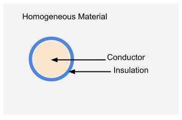
To illustrate the principle, consider a simplified d.c. cable surrounded by insulating material and placed in a homogeneous thermally conducting material.
| I | Conductor current, A |
| R’ | D.c. resistance of the conductor per unit length, Ω/m |
| θ | Maximum conductor operating temperature, °C |
| θa | Ambient temperature, °C |
| Δθ | Temperature difference, θ – θa, K |
| T | Thermal resistance per unit length between conductor and surroundings, K·m/W |
The losses generated by the conductor, in watts per unit length, are:
The heat flow from the conductor, in watts per unit length, is:
At thermal equilibrium, these values are equal. Rearranging gives the current-carrying capacity:
For example, consider a 50 mm2 conductor with XLPE insulation directly buried. If the insulation thermal resistance is 5.88 K·m/W, the soil thermal resistance is 2.5 K·m/W, and the ambient temperature is 25 °C, the total thermal resistance is:
T = 5.88 + 2.5 = 8.38 K·m/W
Using a d.c. resistance of 0.387 mΩ/m and a maximum XLPE conductor temperature of 90 °C:
Δθ = 90 – 25 = 65 K
I = √[65 / (0.000387 × 8.38)] = 142 A
IEC 60287 in more detail
Real cable installations are more complex than the simple example above. Insulating materials have dielectric losses, alternating current introduces skin effect, sheath and eddy-current losses may be present, several cables may generate heat at the same time, and surrounding materials are not always homogeneous.
IEC 60287 addresses these issues, but the equations take care and effort to apply. Anyone using the method for design work should work directly from a copy of the standard.
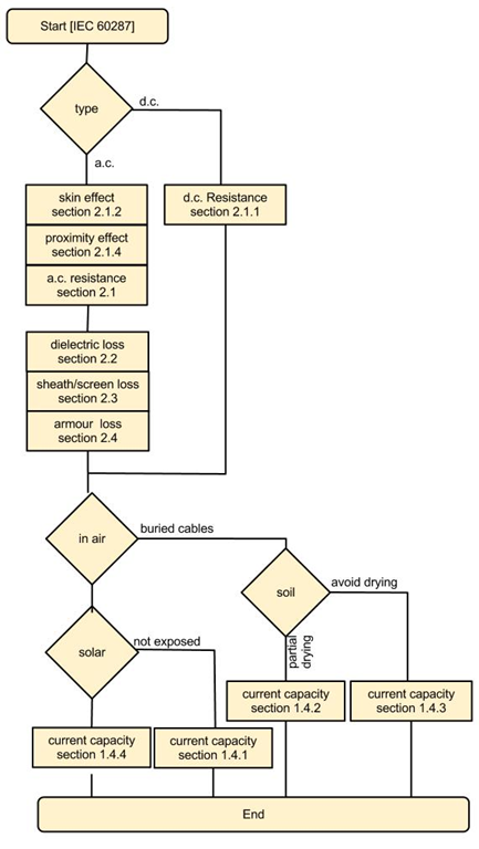
- Differences between a.c. and d.c. systems in current rating calculations
- Critical soil temperatures and the possible need to avoid soil drying
- Cables directly exposed to solar radiation
- Calculation of a.c. and d.c. conductor resistance, including skin effect, proximity effect and operating temperature
- Insulation dielectric losses
- Conductor I2R losses
- Losses in sheaths and screens, including flat, trefoil and transposed formations
- Circulating current losses in sheaths, armour and pipes
- Thermal resistance and its calculation
- Cable troughs and trough air temperature rise
- Derating factors for cables grouped in air
Applying the standard
IEC 60287 includes many equations, so the method can be difficult for engineers who are new to it. A step-by-step approach makes the calculation more manageable, and software is often used because manual calculation is tedious and prone to error.
A cable route may pass through several installation environments, such as a cable basement, ducts in a wall, buried sections, bridge crossings and receiving buildings. In this case, current capacity should be evaluated for each installation condition and the worst case used.
Summary
IEC 60287 reduces current-carrying capacity calculations to a thermal balance problem. The standard provides a detailed framework for calculating cable losses, thermal resistances and installation effects so that the maximum continuous current rating can be determined for the selected cable and route.
For a broader introduction to heat-flow modelling, boundary conditions and FEA, see Cable Thermal Analysis.
For insulation losses used in higher-voltage cable rating calculations, see Dielectric Loss in Cables.
IEC 60287-3-2 also provides a method for life-cycle cost based conductor selection; see Economic Optimisation of Cable Size.
For sheath induced voltage and circulating current mechanisms in single-core cable systems, see Sheath Induced Voltage and Circulating Current.