
IEC 60287-2-2 gives methods for obtaining reduction, or derating, factors for cables installed in free air and protected from solar radiation. The method can be used where an isolated cable rating is already known or as part of an IEC 60287 current-rating calculation.
This article summarises the grouped-in-air method, its assumptions and the calculation sequence. For background, see Cable Derating Factors and IEC 60287 Cable Current Capacity. For design work, use the applicable editions of IEC 60287-2-2 and IEC 60287-2-1 directly.
Scope and assumptions
The IEC 60287-2-2 method is intended for grouped cables running horizontally in free air. Its published data applies within defined limits:
- The cables are protected from direct solar radiation.
- Cables in the group have equal external diameters and emit equal losses.
- Multicore-cable data covers square formations containing up to nine cables.
- Trefoil data covers up to six circuits, with no more than three circuits side by side or two circuits one above another.
- The grouped-cable method neglects dielectric losses.
- Airflow must not be materially restricted by neighbouring objects or the installation arrangement.
Values for cable arrangements outside the published data should be established by suitable test or another justified method. The designer should also confirm that the selected clearances can be maintained along the complete route.
Symbols
| Symbol | Meaning and units |
|---|---|
| De | External diameter of multicore cable, or one single-core cable in trefoil, mm |
| e | Clearance between adjacent cables in a group, measured between surfaces, mm |
| Fg | Group reduction factor |
| h | Heat dissipation coefficient used for thermal resistance calculation, W·m-2·K-5/4 |
| hg | Heat dissipation coefficient of the hottest cable or circuit in a group, W·m-2·K-5/4 |
| hi | Heat dissipation coefficient of an isolated cable or circuit, W·m-2·K-5/4 |
| Ig | Rating of the hottest cable in a group, A |
| It | Rating of one cable or circuit assumed to be isolated, A |
| k1 | Surface temperature rise factor |
| T4g | External thermal resistance of the hottest cable in a group, K·m/W |
| T4i | External thermal resistance of one cable assumed to be isolated while carrying It, K·m/W |
| W | Power loss from isolated cable, or circuit in trefoil, carrying It, W/m |
| Θc | Conductor temperature used for calculating It, °C |
| Θa | Ambient temperature used for calculating It, °C |
Calculation workflow
Where the sustained rating of an isolated cable or circuit is known, the grouped rating can be obtained in the following sequence:
- Establish the isolated rating It and retain the corresponding losses, external thermal resistance and conductor and ambient temperatures.
- Calculate the surface temperature rise factor k1.
- Select the applicable ratio hi/hg from IEC 60287-2-2 Table 1 or Figures 3 to 5, within their stated clearance limits.
- Calculate T4g/T4i iteratively, beginning with (T4g/T4i)1 = hi/hg.
- Calculate the group reduction factor Fg, then obtain the grouped rating Ig.
Equation (4) normally converges quickly. IEC 60287-2-2 notes that one evaluation is usually sufficient. Where hi/hg is less than 1.4, the standard also permits that ratio to be substituted directly for T4g/T4i in equation (1).
Reduction factors for cables grouped in air with existing ratings
First calculate the group reduction factor for the hottest cable or circuit:
The current-carrying capacity of the hottest cable or circuit in the group is then:
The surface temperature rise factor is:
The ratio T4g/T4i is derived iteratively from hi/hg:
Starting with:
Illustrative worked example
This example demonstrates the calculation sequence only. The assumed inputs are not a design recommendation and must not be reused without a project-specific IEC 60287 calculation and the applicable grouping data.
| Input | Illustrative value |
|---|---|
| Isolated rating, It | 500 A |
| Loss, W | 20 W/m |
| Isolated external thermal resistance, T4i | 0.75 K·m/W |
| Conductor temperature, Θc | 90 °C |
| Ambient temperature, Θa | 30 °C |
| Assumed applicable ratio, hi/hg | 1.65 |
Using equation (3), the surface temperature rise factor is:
Starting with (T4g/T4i)1 = 1.65, successive evaluations of equation (4) give:
| Iteration | T4g/T4i |
|---|---|
| 1 | 1.650 |
| 2 | 1.512 |
| 3 | 1.534 |
| 4 | 1.530 |
The ratio has converged to approximately 1.530. Substitution in equation (1) gives:
The illustrative grouped rating is therefore:
In this example, the grouping reduces the isolated rating by about 6%. The result remains dependent on the assumed losses, temperatures, thermal resistance and the selected value of hi/hg.
Reduction factor for IEC 60287 calculated ratings
When IEC 60287 is used directly to calculate sustained current ratings, IEC 60287-2-1 provides the external thermal-resistance method for cables in free air. For the grouped configurations covered by IEC 60287-2-2, substitute the group heat dissipation coefficient hg for the isolated coefficient h:
The applicable ratio hi/hg is obtained from IEC 60287-2-2 Table 1 or Figures 3 to 5. Do not infer values outside the stated arrangements and clearance ranges by extrapolation.
The heat dissipation coefficient h can be obtained from IEC 60287-2-1 formula 2 using the values of constants Z, E and Cg (given in IEC 60287-2-1 table 3).
Selecting grouping data and clearance
IEC 60287-2-2 distinguishes between clearances that make thermal proximity negligible and clearances for which a reduction factor is required. The clearance e is measured between cable surfaces, not between cable axes.
- Table 1 column 2 gives the minimum normalised clearance e/De above which the thermal proximity effect may be neglected.
- If a horizontal clearance cannot be maintained at the applicable value, the method treats the cables as touching and uses the corresponding ratio from Table 1 column 4.
- For vertical arrangements, use Table 1 together with Figures 3 to 5 and remain within the stated clearance range.
- The formulae and curves must not be extrapolated beyond their stated limits.
- Cable supports should maintain the required spacing throughout the route.
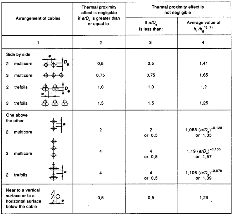
The table identifies the cable arrangement, the clearance above which proximity may be neglected, the lower clearance range for which proximity is significant, and the applicable average value or expression for hi/hg. Always read the table footnotes with the selected value.
Groups installed in more than one plane
Where cables are arranged in both horizontal and vertical planes, determine the grouped rating using the applicable vertical-plane value of hi/hg. The horizontal clearance must also be sufficient to neglect side-by-side thermal proximity, using the relevant value from Table 1.
Related calculations
Grouping is one part of a complete cable-rating assessment. Related topics include IEC 60287 current capacity, sheath and armour losses, and solar-radiation effects. Cable Derating Factors covers the broader application of installation correction factors.
References and limitations
- IEC 60287-2-2, Electric cables – Calculation of the current rating – Part 2: Thermal resistance – Section 2: A method for calculating reduction factors for groups of cables in free air, protected from solar radiation.
- IEC 60287-2-1, Electric cables – Calculation of the current rating – Part 2: Thermal resistance – Section 1: Calculation of thermal resistance.