
In three-phase single-core cable systems, metallic sheaths or armour can have voltage induced in them by the conductor currents. If the sheath or armour is unbonded, or bonded at one end only, the result is an induced voltage at the open end. If both ends are bonded, the induced voltage can drive circulating current in the sheath or armour.
This article sets out a calculation method for estimating sheath induced voltage and circulating current. Although the wording refers to sheaths, the same principles can be applied to armour where the armour forms a metallic return path.
The topic is closely related to Cable Sheath and Armour Losses, because circulating sheath or armour current can add heat and reduce cable current rating.
Induced voltage
The inductive voltage induced per unit length in the sheath of a single-core cable is given by:

with:


For a three-phase set of single-core cables, the method can be expanded to calculate the induced sheath voltage for each phase:


The mutual reactance terms depend on the cable spacing and arrangement:


Circulating currents
Sheath current has two main components:
- Capacitive current: the conductor and sheath, separated by the insulation dielectric, act as a capacitor. Capacitive current flows from the conductor into the sheath and then to earth.
- Inductive current: when sheaths are bonded at both ends, transformer coupling between the conductor and sheath drives a circulating current through the bonded metallic path.
Capacitive current
For a single-core cable, the capacitance is:

Leakage current in the insulation can usually be ignored. The capacitive current for each phase per unit length is then:


For sheaths bonded to earth at one end only, the total capacitive current is found by multiplying the per-unit-length value by the cable length. Where sheaths are bonded to earth at both ends, the capacitive current can flow towards earth in two directions. A simple estimate assumes the current divides equally between the two ends.
Inductive current
If the sheath is bonded at only one end, no inductive circulating current can flow. For sheaths bonded at both ends, the inductive circulating current is estimated by dividing the induced sheath voltage by the sheath impedance:

The sheath resistance can be estimated from:

with the temperature-adjusted sheath resistivity given by:

The sheath reactance depends on the cable configuration. For cables bonded at both ends, the following approximations can be used:
- Trefoil formation:

- Flat formation, no transposition:

- Flat formation, regular transposition:
Sheath voltage and current calculations are sensitive to conductor current, cable construction, installation geometry and any deliberate or accidental parallel current paths. The results from this simplified method should be treated as indicative of magnitude rather than exact measured values.
Cross bonding and transposition
Cross bonding and cable transposition are used to reduce sheath induced voltage and circulating current. Over three sections, the induced voltages are phase shifted by approximately 120 degrees; summing the phase-shifted voltages reduces the overall induced voltage and the resulting circulating current.
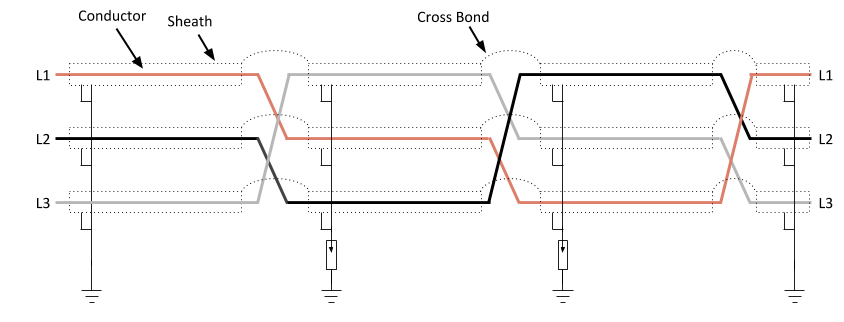
For balanced cables installed in trefoil formation, sheath currents are symmetrical and cross bonding of the sheaths may be sufficient. For flat formation, the induced voltages vary by phase, so cable transposition is normally needed to balance the induced voltages.
References
- Moore, G. Electric Cables Handbook/BICC Cables. Oxford: BSCI, 2000.
- Chen, Wu, Cheng and Yan. Sheath Circulating Current Calculations and Measurements of Underground Power Cables. Xi’an Jiaotong University.
- IEC 60287-1-1, Electric cables – Calculation of the current rating – Current rating equations and calculation of losses.
Symbols
| As | Cross-sectional area of sheath, m2 |
| C | Capacitance, F/m |
| dc | Diameter of the conductor, m |
| ds | Inside diameter of the sheath, m |
| f | Frequency, Hz |
| I | Cable conductor current, A |
| I1, I2, I3 | Conductor phase currents of L1, L2 and L3, A |
| Is1, Is2, Is3 | Sheath phase currents of L1, L2 and L3, A |
| Ls | Sheath inductance, H/m |
| Rs | Sheath resistance, ohm/m |
| S | Distance between cable centres, m |
| S12, S23, S31 | Distances between phase cable centres, m |
| ts | Sheath thickness, m |
| X1, X3, Xa, Xb | Reactance formula terms, ohm/m |
| Xm | Mutual reactance between conductor and sheath, ohm per unit length |
| Xs | Sheath reactance, ohm/m |
| Us | Sheath voltage, V |
| U1, U2, U3 | Phase voltages of L1, L2 and L3, V |
| Us1, Us2, Us3 | Sheath inductive phase voltages of L1, L2 and L3, V |
| αs | Temperature coefficient of sheath resistivity, per degree C |
| η | Sheath/conductor temperature ratio, typically 0.7 to 0.8 |
| ε0 | Permittivity of free space, 8.854187819 x 10⁻¹² F/m |
| εr | Relative permittivity of the dielectric |
| θ | Service temperature of conductor, degree C |
| ρs | Resistivity of sheath, ohm.m |
| ω | Angular frequency, 2πf, s-1 |