
This article is based on a blog post by Steven McFadyen, first published on myElectrical.com on 25 July 2011.
Low voltage power cable selection should combine practical construction choices with current rating, voltage drop and fault withstand checks
Cable sizing often involves repeated decisions. While every installation needs to be checked against its own load, environment and regulatory requirements, low voltage power cable selection can usually start from a consistent practical workflow.
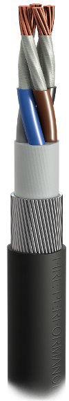
1. Start with a suitable insulation system
For many low voltage power circuits, XLPE is a sensible default insulation choice. It is well established, cost competitive and usually allows a smaller conductor cross-sectional area than lower-temperature insulation systems. Other insulation types, such as PVC or rubber, may still be appropriate where the environment, flexibility, fire performance or project specification requires them.
For material background, see Cable Insulation.
2. Decide whether armouring is needed
For buried cable routes, mechanical protection is usually essential, so armoured cable is often the practical choice. For indoor routes, armouring may not be necessary, although it can sometimes be used as the circuit protective conductor where permitted by the design standard and local practice.
The decision should reflect installation method, mechanical risk, earthing requirements and project standards.
3. Consider LSZH sheathing
Low smoke zero halogen sheathing can reduce smoke and acidic gas emissions during a fire. It is often preferred in occupied buildings, tunnels, public infrastructure and locations where escape routes or sensitive equipment may be affected by smoke or fumes.
4. Calculate current-carrying capacity
Calculate the cable current rating using an acceptable method for the installation. In the UK, BS 7671 is commonly used for low voltage installations; other projects may use IEC, utility, client or local standards.
The rating should consider the design current, protective-device rating, installation method and any applicable derating factors such as ambient temperature, grouping, soil conditions or enclosure effects.
Useful related topics include Cable Derating Factors and IEC 60287 Cable Current Capacity.
5. Check voltage drop
Voltage drop should be checked from the source through to the final load. Where a circuit includes several cable sections, the total voltage drop is the sum of the drops in each section.
The allowable limit depends on the applicable regulation or project requirement. For BS 7671-specific calculations, see BS 7671 Voltage Drop Calculations; for the general method, see Voltage Drop Calculations for Cable Sizing.
6. Check fault withstand
The selected conductor and any protective conductor, sheath or armour used as part of the earth-fault path must withstand the prospective fault current until the protective device operates. This is often straightforward for larger cables, but it can govern the size of smaller conductors or protective conductors.
For more detail, see Cable Thermal Withstand Under Fault Conditions.
7. Use calculation software carefully
Cable sizing software can make repeated calculations faster and more consistent, especially where multiple design checks interact. The software output should still be reviewed against the installation assumptions, protective device data, local standards and engineering judgement.
For the wider calculation context, see Cable Sizing: Current Capacity, Voltage Drop and Fault Withstand.
8. Be practical
If the calculation produces an unexpectedly large cable, step back and review the system design. A very large cable on a small load may indicate an excessive route length, unsuitable supply arrangement, voltage drop issue, protection mismatch or another design constraint that should be addressed directly.
The same basic method may cover many low voltage power circuits, but it does not cover every case. Special loads, unusual environments, high fault levels, parallel circuits, harmonic content, fire requirements and utility or client specifications can all require additional checks.
Summary checklist
- Select a suitable insulation system.
- Decide whether armouring or mechanical protection is required.
- Consider LSZH or other sheath requirements.
- Calculate current-carrying capacity and apply derating factors.
- Check voltage drop from source to load.
- Check short-circuit and earth-fault withstand.
- Use calculation software to improve consistency, but review assumptions.
- Sense-check the result against the practical design.
Once a few representative circuits have been selected, many similar circuits can often be sized more efficiently. Even so, each final selection should still be checked against its own load, route, environment and protection arrangement.