Power cable construction describes the conductors, insulation and protective layers that make up a cable. Understanding these parts helps you interpret a cable datasheet, compare products and select the correct inputs for cable sizing.
This guide explains common terminology for low-voltage (LV) and medium-voltage (MV) power cables, with an emphasis on modern extruded-insulation designs. Other constructions, including paper-insulated, mineral-insulated and specialist cables, use different arrangements. Always check the construction stated for the actual product.
Conductor, core and cable: what is the difference?
- Conductor: the metallic part that carries current. It may be one solid wire or an assembly of strands.
- Strand: one of the individual wires making up a stranded conductor.
- Core: a conductor with its insulation and, where applicable, its associated screens.
- Cable: the complete assembly, which may contain one core or several cores together with the specified coverings and protective layers.
A single-core cable can contain a solid conductor or a stranded conductor: “single-core” does not mean it must be a “solid conductor”. Similarly, a four-core cable normally contains four insulated conductors, rather than a conductor made from four strands.
Typical low-voltage armoured cable construction
A typical multicore XLPE-insulated armoured power cable has insulated conductors assembled together, an inner covering or bedding, wire armour and an outer sheath. Fillers and tapes may support the assembly. The exact materials and sequence depend on the cable standard and manufacturer.
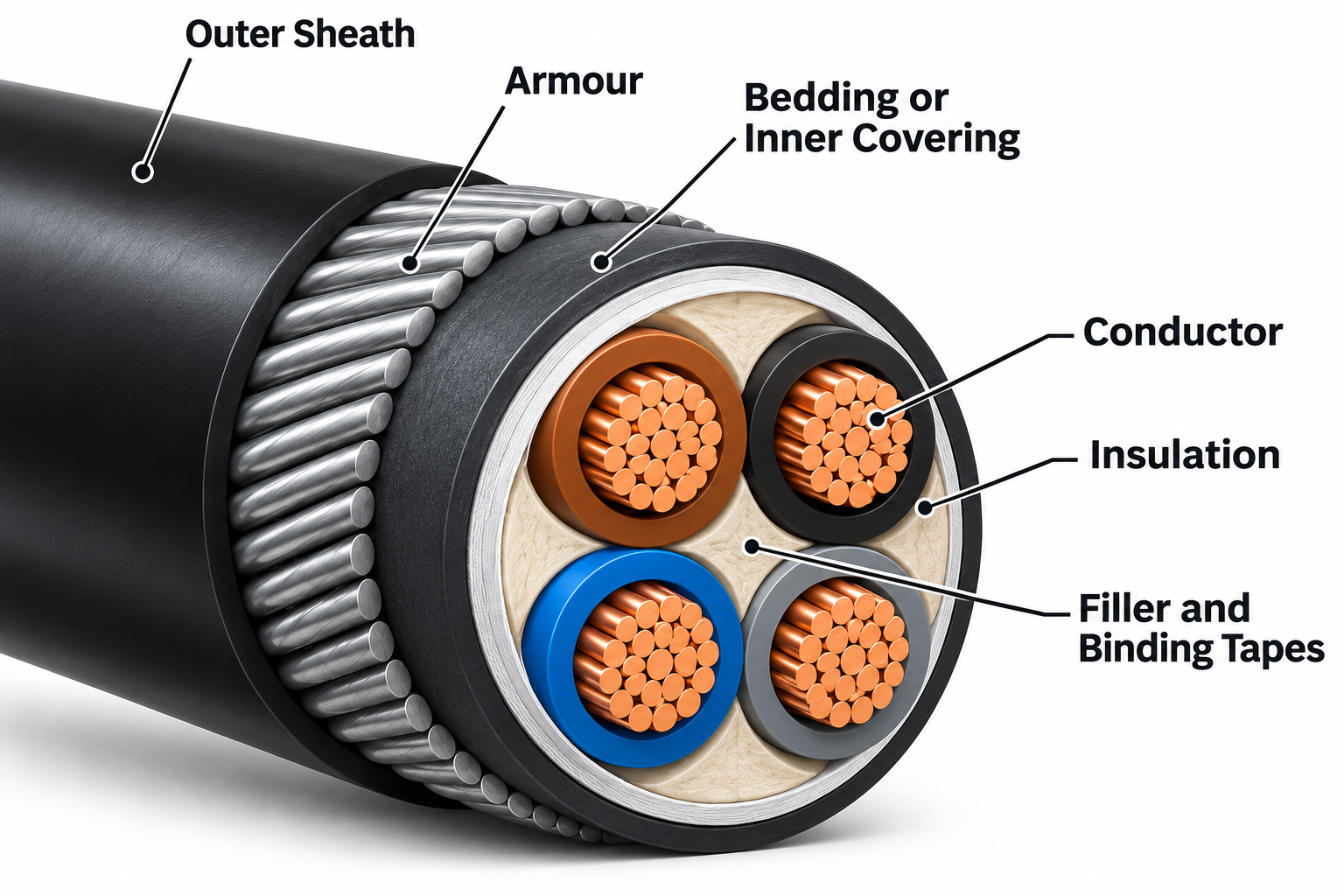
| Part | Main purpose | Common terminology |
|---|---|---|
| Conductor | Carries the circuit current. | Copper (Cu) or aluminium (Al); solid or stranded. |
| Insulation | Provides electrical separation around each conductor. | PVC, XLPE or EPR, depending on the product. |
| Fillers and binding tapes | Support the laid-up cores and help form a stable assembly. | Fillers, binders and separators; their arrangement varies. |
| Bedding or inner covering | Provides a layer beneath the armour and protects the underlying assembly. | May be extruded or use other coverings, as specified. |
| Armour | Provides mechanical protection. | Steel wire armour (SWA), aluminium wire armour (AWA), or other armour constructions. |
| Outer sheath | Forms the external protective covering. | Oversheath or jacket; examples include PVC, PE, or LSZH compounds. |
“Sheath” needs context. It can refer to an outer polymer covering, but “metallic sheath” describes a different component. Look for the material and position in the construction drawing.
Insulation and sheath are different layers
Insulation surrounds the conductor and provides the required electrical separation. The outer sheath protects the complete assembly against the conditions for which the cable is designed. Do not treat the sheath as the cable’s main electrical insulation.
Calling a cable “XLPE” usually identifies its insulation. It does not mean that every polymer layer is XLPE. An XLPE-insulated cable can have PVC bedding and a PVC outer sheath.
For a comparison of the main material types, see Cable Insulation: Thermoplastic and Thermosetting Materials.
What changes in a medium-voltage screened cable?
A typical extruded-insulation MV cable adds screening layers around the insulation system. These layers help control electrical stress and provide a metallic connection to earth through the designed bonding arrangement.
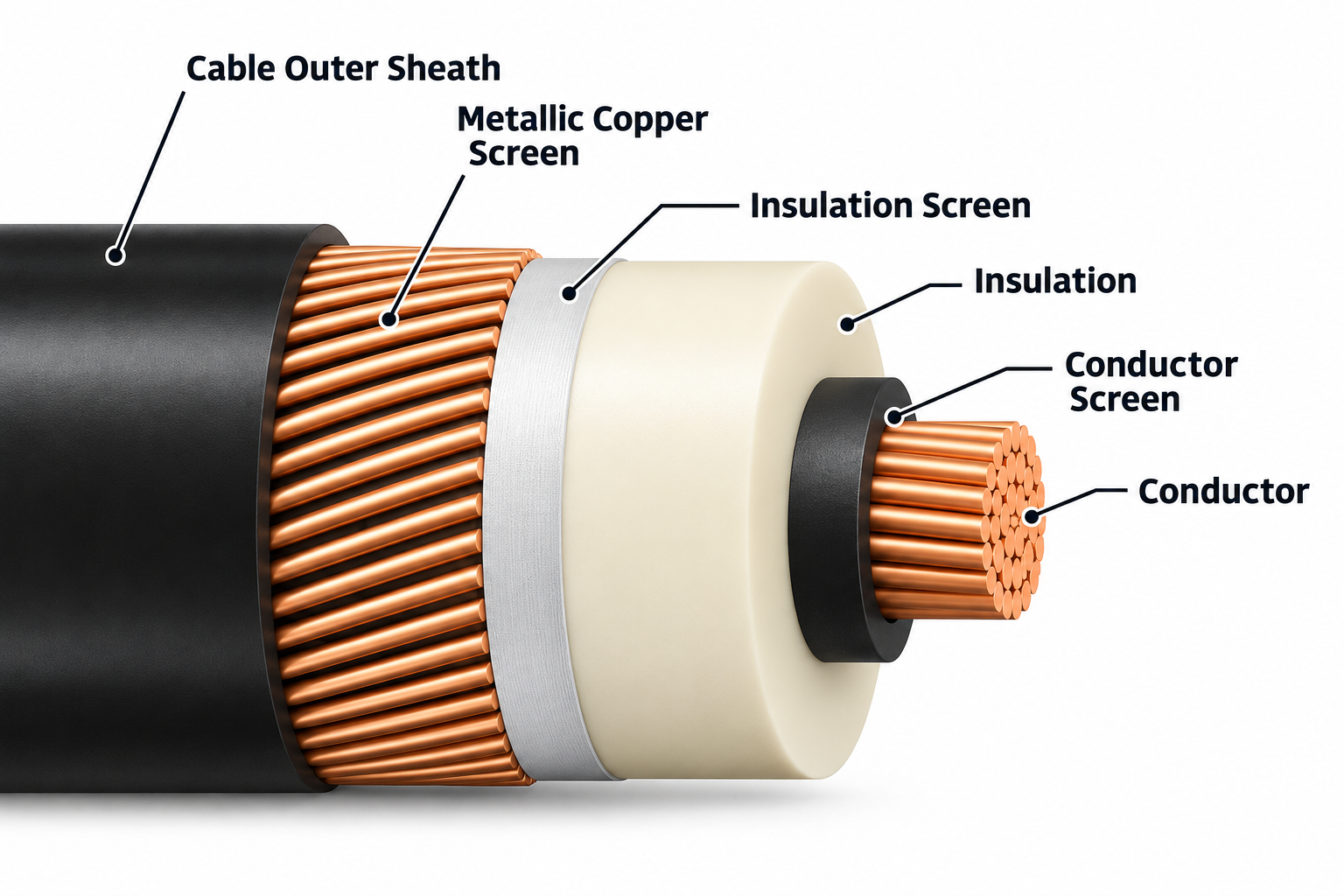
- Conductor screen: a semiconducting layer between the conductor and insulation that provides a smooth electrical interface.
- Insulation: the main dielectric layer, commonly XLPE or EPR in modern extruded designs.
- Insulation screen: the semiconducting layer outside the insulation.
- Metallic screen: a conductive layer, such as copper wires or tape, connected to earth through the specified bonding system.
The semiconducting layers and metallic screen have different functions and are not interchangeable. Terminology varies: some specifications use “insulation screen” for the combined semiconducting and metallic screening arrangement. Read the manufacturer’s layer-by-layer description.
Outside the screened core, the cable may include water-blocking materials, a metallic sheath, bedding, armour and an outer sheath. Not every MV cable contains all of these layers.
Screen, metallic sheath and armour
A metallic screen forms part of the cable’s electrical screening and earthing arrangement. Its fault-current capability and bonding require deliberate design. Depending on its construction, a metallic sheath may also provide a moisture barrier.
Armour primarily provides mechanical protection. Where permitted and properly designed, armour may also form part of the protective-conductor path. Its presence alone does not prove that its electrical continuity, impedance or fault withstand is adequate.
For the protective-conductor role, see Circuit Protective Conductor (CPC) in Cable Sizing. For their effect on current rating, see Cable Sheath and Armour Losses.
SWA and AWA
SWA means steel wire armour; AWA means aluminium wire armour. In common power-cable constructions, SWA is used on multicore cables and non-magnetic AWA on single-core AC cables. Magnetic armour surrounding an individual AC phase can introduce substantial additional losses.
Do not confuse armour with the conductor material. A copper-conductor cable can have aluminium wire armour.
Conductor construction and size
Copper and aluminium are common conductor materials for power cables. Conductors may be circular, compacted, sector-shaped or, in larger designs, segmental. These terms describe construction or geometry; they do not replace the material, size or resistance specification.
IEC 60228 conductor classes commonly encountered are class 1 (solid), class 2 (stranded), class 5 (flexible) and class 6 (more flexible than class 5). Flexibility class alone does not mean the entire cable is suitable for repeated movement.
Cross-sectional area (CSA), usually expressed in mm², is a nominal conductor size. It is not the cable’s overall diameter, and you cannot determine a cable’s current rating from CSA alone.
See Conductor Resistance for conductor classes and resistance values, and Standard Cable Sizes to IEC 60228 for metric sizes.
Common cable abbreviations
| Term | Meaning | What to check |
|---|---|---|
| Cu / Al | Copper / aluminium. | Whether the description refers to the conductor, screen or armour. |
| PVC | Polyvinyl chloride. | Which layer uses it: insulation, bedding or sheath. |
| PE / XLPE | Polyethylene / cross-linked polyethylene. | The specified material and layer; XLPE is a thermosetting insulation. |
| EPR | Ethylene-propylene rubber. | The particular compound and declared cable ratings. |
| SWA / AWA | Steel wire armour / aluminium wire armour. | Armour material and suitability for the circuit. |
| LSZH / LSOH | Low smoke zero halogen / low smoke zero halogen. | The complete cable’s declared tests and performance, not just the abbreviation. |
| CSA / OD | Cross-sectional area / overall diameter. | CSA normally describes the conductor; OD describes the complete cable. |
| CPC | Circuit protective conductor. | Its actual form, continuity, impedance and fault withstand. |
Low smoke, halogen content, flame spread and circuit integrity during fire are separate characteristics. An LSZH description alone does not establish a cable’s fire-resistance performance or its CPR classification. See Halogen-Free Cable Compounds and CPR: Construction Products Regulation for Cables for related topics.
How to read a cable description
Consider this illustrative description: 4 × 95 mm² Cu/XLPE/SWA/PVC, 0.6/1 kV.
- 4 × 95 mm²: four cores, each with a nominal conductor CSA of 95 mm².
- Cu: copper conductors.
- XLPE: cross-linked polyethylene insulation.
- SWA: steel wire armour.
- PVC: PVC outer sheath in this description.
- 0.6/1 kV: the cable’s rated voltage designation.
This is shorthand, not a complete purchase specification. It may omit bedding, conductor class, screen details, fire performance, the manufacturing standard and other requirements. A core count does not establish whether a core is intended as a phase, neutral or protective conductor; check identification and the circuit design.
Understanding U₀/U (Uₘ) voltage ratings
For AC power cables, voltage ratings are commonly expressed as RMS values in the form U₀/U, sometimes followed by (Uₘ):
- U₀: rated voltage between an insulated conductor and earth or the metallic covering.
- U: rated voltage between conductors.
- Uₘ: the highest system voltage for which the equipment may be used.
For example, 6.35/11 (12) kV gives U₀ = 6.35 kV, U = 11 kV and Uₘ = 12 kV. These figures describe the voltage rating, not current capacity or an impulse withstand level. Selection also depends on the system earthing arrangement, earth-fault duration and applicable cable standard. Do not infer a DC rating from an AC designation.
Why construction matters for cable sizing
Two cables with the same conductor CSA can have different ratings and installation requirements. Construction affects several checks:
- Current capacity: insulation temperature limits, conductor losses and heat flow through the layers affect the allowable current.
- Voltage drop: conductor material, operating temperature and arrangement affect resistance and reactance.
- Fault withstand: conductors, screens and any armour used as a protective path need suitable thermal capability.
- Installation: overall diameter, weight, bending radius, pulling limits and environmental protection depend on the actual cable.
Once the construction is understood, follow 8 Steps to Low Voltage Power Cable Selection and Sizing to work through the design checks. Use the manufacturer’s datasheet and the applicable design standard for the final selection.
References and further reading
- IET Wiring Matters: Thermoplastic (PVC) or Thermosetting (XLPE) SWA cable? — LV construction and material distinctions.
- Eland Cables: BS 6622 XLPE PVC 8.7/15 kV datasheet — an example of separately specified screening and protective layers.
- Prysmian: Medium Voltage Systems — construction variants and metallic screens.
- Eland Cables: What is voltage rating? — voltage designation terminology.
- IEC 60228, Conductors of insulated cables, and the applicable part of IEC 60502 for the cable being specified. For an introduction to voltage-range coverage, see IEC 60502 vs IEC 60840.