
Cables
This myCableEngineering software cables guide explains how to create, edit and size cables in myCableEngineering. For the project-level workflow, see Projects. For the engineering background behind the calculations, see Cable Sizing.

You can create and size cables for your projects. To add a new cable, click the ‘+Cable’ button. Once a cable is added, you can edit and size it.
In addition to navigating to a project’s cables from the project’s view, you can also use recent project links on the dashboard.
Schedule and Actions
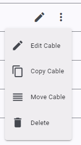
Your cables are listed in a table. You can filter what is displayed by typing search terms and sort the table by clicking on headings. You can select cables using the tick boxes. For each cable row, you can do the following actions:
- edit – edit the cables’ details
- copy – copy the cable
- move – move a cable to another project
- delete – delete the cable
You can also use the action buttons at the top of the page to report, delete, copy or move multiple selected cables.
By default, when using reports, all cables are printed. Only selected cables are printed if one or more cables are selected.
Cable Edit Form
The cable edit form is split into sections and follows a logical design pattern. The form is dynamic, and selections or fields will change depending on the choices made. This ensures the form is easy to use and only the necessary data is entered.
Cable Description
To keep track of your cable, provide a meaningful designation, the start point, the end point, and a useful description.
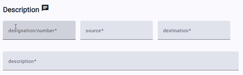
Hovering over the message icon displays the cable’s unique reference identifier. Clicking on the icon copies the identifier to the clipboard. Please include the identifier in any support request.
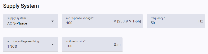
Supply System
You can select either an a.c. or a d.c. supply. Depending on the supply type, you must provide the voltage, frequency, number of phases, and earthing system type. Changing the voltage may change the selection of available cables.
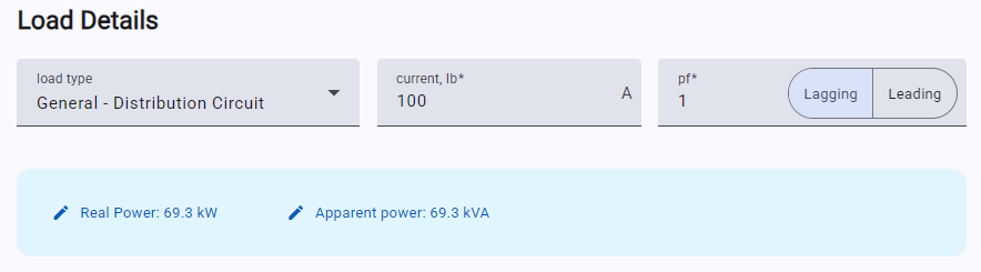
Load Details
Select the type of load your cable will be used with, and provide the anticipated maximum current which will flow in the cable (including the power factor). You can also enter the kW or kVA, and the application will calculate the load current.
Protection
You can select a protective device and trip unit for your cable. If selected, the current capacity will be based on the protective device settings. For adjustable protective devices, you can enter a setting below the trip unit rating by using the ‘Ir’ slider.
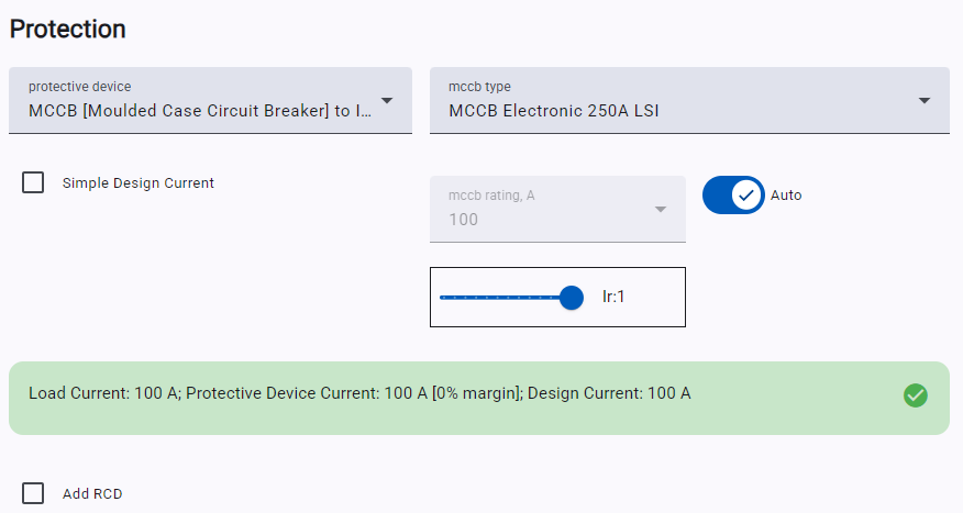
If required, you can add an RCD using the ‘Add RCD’ checkbox and select an appropriate rating from the dropdown. Selecting “Simple Design Current”, will not take the protective device overcurrent rating into account when determining the design current for capacity calculations.
Cable Selection
You can select the cable you would like to use from a selection of generic and manufacturer cables. The selected voltage and system type determine the available cables.
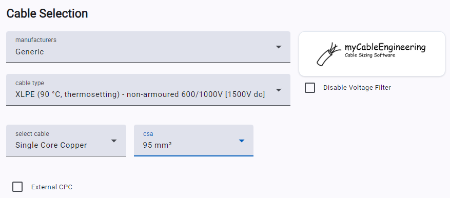
If required, you can add an external CPC. Options to select a spare core for CPC and specify screen or armour bonding appear when appropriate cables are selected. In normal use, the list of cables is filtered to show only voltage-relevant cables. This can be disabled, allowing you to select higher voltage cables.
CSA – select the correct value from the dropdown box if you know which CSA you wish to use. If you wish to calculate the CSA, select any value. Once sufficient data is entered and the sizing method selected, the calculation results will suggest a suitable CSA.
Installation
Depending on voltage, selected cables and configuration details, sizing standards may be available. It is possible that no sizing standard covers your cable type; in that case, only UDR is available.
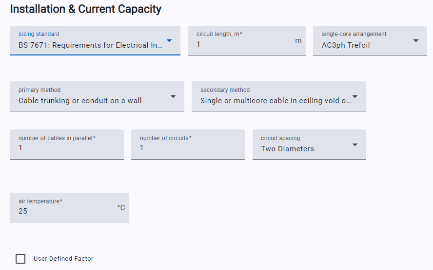
Depending on the selected standard and installation method, appropriate fields will show, allowing you to enter the necessary installation details. You also enter an additional “User Defined Factor”, which will be applied during capacity calculations.
The application only uses installation methods defined in the sizing standard. The methods in the standard may not cover your specific installation requirements. In this event, you can try a different sizing standard.
Note: ‘Circuits’ is the number of independent cable circuits being run together (include this cable as 1 circuit, plus any additional circuits).
Summary information is shown for the entered installation factors. This allows you to quickly evaluate the effects of various installation methods. The suggested CSA is the minimum cable size (based on the installation choices) that meets the requirements of the sizing standard.
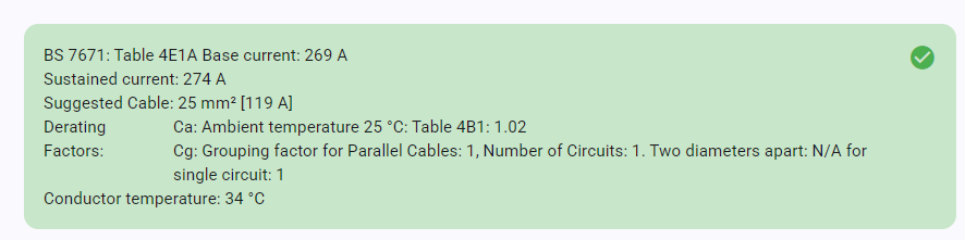
The available cable CSA is based on manufacturing standards and what manufacturers provide. For a given sizing standard, the CSA that can be sized is determined by the values in the standard. It may be that the sizing standard does not cover the selected CSA. In this event, the summary box will display an appropriate message.
User Defined Rating [UDR]
User-defined rating is always available and is the default option. This is used to specify the value of sustained current capacity for the cable, the temperature, and the conditions under which this rating applies.
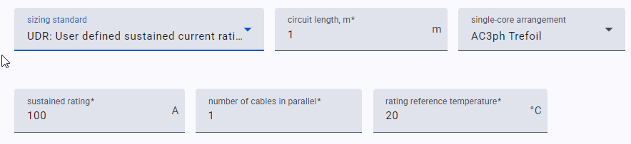
UDR allows you to keep track of cables for which the sustained current capacity is determined by other means. Any entered UDR is used in subsequent impedance, voltage drop, and fault-rating calculations.
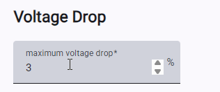
Voltage Drop
Enter the maximum allowable voltage drop for your system. This is primarily used to provide a notification if the calculated value exceeds the required maximum.
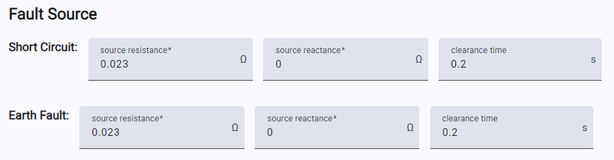
Fault Rating
Provide the expected line-line and line-earth fault ratings (either in kA or impedance), along with the power factor and time before the fault is cleared.
Earth Fault Loop (EFL)
Earth Fault Loop calculations for certain LV cables can be performed once a protective device is selected. In many cases, the maximum allowable EFL impedance is automatically calculated. Where this is not the case, or should you wish to use a different value, this can be entered.
To reduce EFL impedance, you can choose or add an external CPC or use a spare core if one is available. It is also possible to select to ignore any cable armour in EFL calculations.
Reasoning/Comments
You can enter comments or information about your cable here. Comments are printed on various reports. Comments are ideal to document your findings, assumptions, and other relevant cable information.
Related Calculation Notes
The software uses the project and cable inputs to support checks such as voltage drop, fault calculations, earth fault loop impedance, and power loss. These articles explain the engineering methods behind the software results.
For navigation and account-level help, return to myCableEngineering Software Basics.