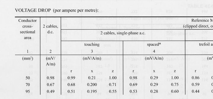
BS 7671 Voltage Drop

Last updated on 2017-07-16 4 mins. to read

BS 7671 , Appendix 4 (Informative), gives a procedure for calculating the voltage drop in low voltage cables.  This procedure is based on looking up resistive and reactive voltage drops in a table and determining the cable voltage drop from these values.

Voltage Drop Calculation

The tables in BS 7671 give the voltage drops for different cables in mV/A/m (or effectively mΩ/m) for various cable types and installation arrangements.  Voltage drop figures are related to the cable's maximum operating temperature and the line to neutral voltage for single phase circuits and line to line voltage for three phase circuits. Values for both resistive (R), reactive (X) and total impedance (Z) voltage drops are given.


Typical BS 71 Voltage Drop Table

Note: the figures in the tables apply to frequencies from 49 to 61 Hz for a.c. cables and assume armour is bonded at both ends for single core armoured cables. For conductors less than 16 mm2, the tables ignore inductance and only resistive voltage drops are given.

Typically the cable voltage drop is found by multiply the figures given in the table by the intended cable operating current and its length.  This approach leads to significant inaccuracies where the cable is operating substantially below its rated value due to the cable having a lower operating temperature.  If power factor is not correctly considered, errors in calculated voltage drop will also be apparent.  

Only the resistance of the cable is affected by temperature.  To correct the for the operating temperature of the cable, we can use:

Ct=230+tp-Ca2Cg2Cs2Cd2-Ib2It2tp-30230+tp

tp        - the maximum permitted normal operating temperature of the cable
Ib        - design current of the circuit (current intended to be carried by the cable)
It         - value to tabulated current (BS 7671 appendix 4, tables)
Ca       - rating factor for ambient temperature
Cg       - rating factor for grouping
Cs       - rating factor for soil thermal resistivity
Cd       - rating factor for depth of burial

Combining the temperature correction factor, with the power factor,cos(ϕ) the voltage drop (in mV) is given by:

vd =Ib*L*Ct cos(ϕ) (tabluated(mV/A/m)r) + sin(ϕ) (tabulated(mV/A/m)x)

vd             - voltage drop across the cable in mV (divide by 1000 for V)
cos(ϕ)   - the power factor of the circuit
L               - length of the cable, m

Note: power factor is 1 and the tabulated (mV/A/m)x is 0 for a d.c. circuit. For cable CSA less than 16 mm2, BS 7671 ignores inductance and (mV/A/m)x can be taken as zero. For three phase circuits, the voltage drop is related to the line-line voltage - to relate to the line-neutral voltage divide by √3.

To obtain the voltage drop as a percentage, divide by the nominal voltage for d.c. circuits, the line-neutral voltage for single phase circuits and the line-line voltage for three phase circuits.

From BS 7671 Appendix 4, Table 4Ab, the voltage drop between the origin of any installation and load point should not be greater than:

Allowable Voltage Drop
  Lighting Other Uses
Low voltage installation supplied directly from a public LV distribution system 3% 5%
Low voltage installation supplied from a private LV supply 6% 8%

Note: for installation runs longer than 100 m, the above can be increased by 0.005% per metre beyond 100m, without any increase being greater than 0.5%.

Example Calculation

To illustrate the above, consider a single core, 50 mm2 copper XLPE armoured cable, supplying a 400 V three phase load of 152 A with pf=0.87.  Assume the cable is installed in trefoil on a ladder with an ambient of 35 °C, not grouped with any other cables and 80 m in length. 

To view the detailed calculation for the cable, please see BS 7671 Voltage Drop Calculation.  This calculation shows that the absolute voltage drop is 10.06 V (referenced to the line-line voltage).  As a percentage the voltage drop is 2.52%.

myCableEngineering.com - sizing the same cable with myCableEngineering, using a generic cable gives the same voltage drop (10.07 V and 2.52%). Using a BS 6724 cable gives 2.46%.  These types of variation are due to BS 7671 using a one-size-fits-all approach, whereas in myCableEngineering voltage drop is calculated based on each cables actual physical characteristics.

Deriving Impedance & CENELEC 50480

Voltage drop in cables is always related to the impedance of the cable.  Consequently, it is possible to drive an equivalent impedance for the mV/A/m values given in the BS 7671 tables. To convert the three phase table values so that they relate to the input resistance (or reactance) required by CENELEC 50480 it is necessary to divide the BS 7671 three phase values by √3 (the square root of three).  No adjustment is required for single phase values.  

Given values of voltage drop for three phase balanced systems are related to the line voltage.  

R = (mV/A/m)r / (2*1000) and X = 0
        - for a d.c. circuit

R = (mV/A/m)r / (2*1000) and X = (mV/A/m)x/(2*1000)
        - for a singe phase a.c. circuit

R = (mV/A/m)r / (3*1000) and X = (mV/A/m)x/(3*1000)
        - for a singe phase a.c. circuit

(mV/A/m)r        - tabulated resistive mV/A/m from BS 7671
(mV/A/m)x        - tabulated reactive mV/A/m from BS 7671
R                      - resistance per conductor in  Ω/m
X                      - reactance per conductor in Ω/m

Note: the values given in BS 7671 for resistive voltage drop are at the cables maximum operating temperature (i.e. 90 °C for thermosetting cables).  These can be adjusted to the required temperature by standard formulae.  See Conductor Resistance for details on how to adjust for temperature.


Comments

May 10, 2018 5:27 PM
When using volt drop calculations with mV/Ampere/metre values from Table 4D4B,  if working with DC or Single phase AC must I multiply the cable length by 2 to get the VD for the supply and return conductors?

Or do  the mV/A/m values for Two core Cable DC and Two core cable Single AC already include the VDrop for supply & return conductors, so I only use the length of the cable?

regards

Gerry Stewart
Steven McFadyen May 11, 2018 11:23 AM
The tables in BS 7671 are for all conductors.  You do not need to multiply by 2.   Just use the values given in the table and multiple by the length of the run. The details are explained in appendix 4, section 6 of the standard.
Shubham Rekhate Jul 30, 2018 7:21 AM
Hi, Steven.
I also had the same question if the value is to be multiplied by 2 or not. But even after reading your answer I'm not clear.
Can you please explain what "the length of the run" mean in single phase and also in three phase circuits? Is it the to and fro length or only one way length?
Thanks.
Ben ------ Jun 19, 2023 2:27 PM
Hi could you explain where the 230 in the formula comes from? I've seen the formula using Cos theta and Sin theta before but the 230 is new to me.
Steven McFadyen Jun 20, 2023 9:57 AM
It is from BS 7671, Appendix 4.