
Convection is one of the heat-transfer mechanisms that can affect cable temperature, particularly for cables installed in air, in ventilated spaces or inside enclosures. In cable thermal models it is commonly treated as a boundary condition at a surface.
This article expands the convection part of Cable Thermal Analysis. It is most relevant where cable heat transfer is not dominated by conduction through soil, backfill or solid installation materials.
Newton’s law of cooling
For natural or forced convection in a gas or liquid, Newton’s law of cooling is used:
For air, a common cable installation medium, the convection heat-transfer coefficient h for air flowing at velocity v can be estimated from:
A convection boundary can be represented using a Neumann condition, with q set to the desired convection coefficient and g set to the environmental temperature multiplied by that coefficient.
Convection in enclosed spaces
Convection is a complex heat-transfer topic because it depends on fluid flow, gas properties and surface geometry. For cable sizing, modelling the full fluid-flow behaviour is often impractical. A common simplification is to use an effective thermal conductivity so that the enclosed air can be treated using conduction-style heat transfer.
For an enclosed space, the effective thermal conductivity is:
The Grashof number for the enclosure is:
The coefficient of thermal expansion and film temperature are given by:
The film temperature Tf should be expressed in Kelvin, not degrees Celsius.
Experimental results for free convection in an enclosure can be represented by:
Air properties
Typical air properties for free-convection calculations are:
| Tf, °C | ν, 10-5 m2/s | Pr |
|---|---|---|
| 0 | 1.343 | 0.720 |
| 20 | 1.568 | 0.708 |
| 80 | 2.056 | 0.697 |
| 120 | 2.591 | 0.689 |
For other temperatures, use suitable air-property data for the expected film temperature.
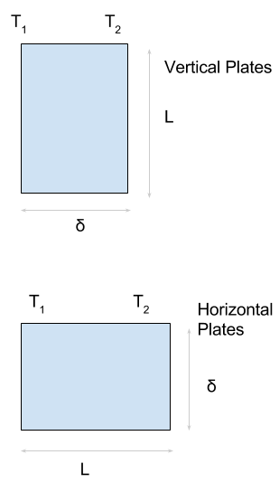
Free-convection correlation factors
The coefficients C, n and m are selected from experimental correlation data using the Grashof-Prandtl product. In the original data, δ is the hydrodynamic boundary-layer thickness.
| Geometry | GrδPr | Nuδ | Pr | L/δ | C | n | m |
|---|---|---|---|---|---|---|---|
| Vertical plate | < 2,000 | 1.0 | |||||
| Vertical plate | 6,000-200,000 | 0.2-2 | 11-42 | 0.197 | 1/4 | -1/9 | |
| Vertical plate | 200,000-1.1 x 10⁷ | 0.5-2 | 11-42 | 0.073 | 1/3 | -1/9 | |
| Horizontal plate | < 1,700 | 1.0 | |||||
| Horizontal plate | 1,700-7,000 | 0.5-2 | 0.059 | 0.4 | 0 | ||
| Horizontal plate | 7,000-3.2 x 10⁵ | 0.2-2 | 0.212 | 1/4 | 0 | ||
| Horizontal plate | > 3.2 x 10⁵ | 0.5-2 | 0.061 | 1/3 | 0 |
Symbols
| A | Area, m2 |
| g | Acceleration due to gravity, m/s2 |
| h | Convection heat-transfer coefficient, W/m2.°C |
| k | Thermal conductivity, W/m.°C |
| ke | Effective thermal conductivity, W/m.°C |
| T, T1, T2, Ta | Temperature, K |
| v | Air velocity, m/s |
| ν | Kinematic viscosity, m2/s |
| q | Heat flow, W |
| Heat generated per unit volume, W/m3 | |
| β | Coefficient of thermal expansion |
| δ | Enclosure dimension, m |
| Gr | Grashof number |
| Nu | Nusselt number |
| Pr | Prandtl number |
| Ra | Rayleigh number |