
When sizing a.c. cables, heat generated by losses in metallic sheaths, screens and armour may need to be included in the current rating calculation. If these losses are significant, they reduce the allowable current-carrying capacity of the cable.
This article summarises the sheath and armour loss factors used in IEC 60287 calculations. The formulae below are reference equations; for design work, the relevant edition of IEC 60287 and the cable manufacturer’s data should be used directly.
Sheath and armour loss components
The sheath or screen loss factor, λ1, consists of circulating-current loss and eddy-current loss:
- λ1′ represents circulating-current losses. These occur in single-core cables where sheaths are bonded at two or more points along the route.
- λ1″ represents eddy-current losses caused by changing magnetic fields.
- λ2 represents armour loss.
Sheath and armour losses are applicable to a.c. cables. The formula used depends on cable construction, bonding, armour type and installation arrangement.
Single-core cable sheath or screen loss
For installations bonded at one point only, circulating currents are not possible and circulating-current loss is zero. Except for large segmental conductors, eddy-current loss in single-core cables is normally small enough to ignore.
Trefoil or flat formation with transposition, bonded at both ends
Flat formation without transposition, bonded at both ends
For the outer cable with the greater losses:
For the outer cable with the lower losses:
For the middle cable:
Multicore cable sheath or screen loss
For multicore cables with a sheath or screen surrounding all cores, circulating current loss is ignored. Eddy-current loss, λ1″, may still need to be considered.
Two-core cable with common sheath, unarmoured
For round or oval conductors:
For sector-shaped conductors:
Three-core cable with common sheath, unarmoured
For round or oval conductors, Rs ≤ 100 µΩ/m:
For round or oval conductors, Rs > 100 µΩ/m:
For sector-shaped conductors:
Two-core or three-core cable with steel tape armour
Multiply the unarmoured cable factor by:
Cables with each core in a separate sheath or pipe-type cables
Armour loss
For non-magnetic armour, use the equation for λ1″, substituting the parallel combination of sheath and armour resistance for Rs, and the root mean square of sheath and armour diameter for d.
General advice is not to use magnetic armour for single-core cables. If it is required, use the detailed guidance in IEC 60287.
Two-core cable with steel wire armour
Three-core cable with steel wire armour
For round conductors:
For sector-shaped conductors:
Calculating sheath and armour resistance
Sheath and armour resistances used in the loss equations are calculated at their operating temperature.
For the cable sheath or screen temperature:
For armour temperature:
For sheath or screen resistance:
For armour resistance:
For dielectric loss, refer to the IEC 60287 dielectric loss calculation for the cable construction being assessed.
Cable reactance estimates
For single-core cables with significant conductor spacing, reactance is needed when calculating circulating-current loss. Accurate values should be obtained from the cable manufacturer or calculated with suitable software. The following equations can be used for estimates in Ω/m.
For trefoil or flat formation without transposition:
For flat formation with transposition:
For mutual reactance of flat formation cables:
For steel tape armour resistance, the winding method matters. Longitudinal tapes can be treated as an equivalent cylinder; tapes laid at about 54 degrees to the cable axis may use twice that value; very short lay tapes may be treated as infinite resistance, with losses neglected; and double-layer short-lay tapes may use twice the equivalent-cylinder value.
Cable transposition and cross bonding
Transposition is used to reduce circulating currents in single-core cable sheaths and improve cable rating. Cross bonding makes induced sheath currents oppose each other, reducing the net circulating current.
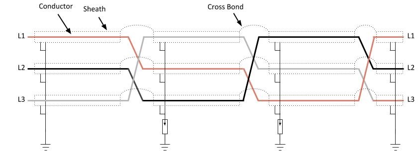
Intermediate transposition points normally include overvoltage protection to protect the cable and personnel if voltage builds up during a fault. In practice, three minor sections between cross-bonding points form a major section with three full transpositions, often arranged at cable joint positions or drum lengths.
Special situations
Large segmental conductors
Eddy-current losses in single-core cables are normally small relative to other losses and can often be ignored. For large segmental conductors, eddy-current loss should be considered and may be derived from the circulating-current loss factor:
Variation of route spacing
If spacing is not maintained for the full cable route, reactance varies along the route. An equivalent overall reactance can be calculated from:
In this expression, la, lb, … are section lengths and Xa, Xb, … are the reactances of each section.
Symbols
| A | Armour cross-sectional area, mm2 |
| R | Conductor a.c. resistance, Ω/m |
| RA | Armour resistance at maximum operating temperature, Ω/m |
| RA20 | Armour resistance at 20 °C, Ω/m |
| Rs | Sheath or screen resistance at maximum operating temperature, Ω/m |
| Rs20 | Sheath or screen resistance at 20 °C, Ω/m |
| X | Sheath or screen reactance, Ω/m |
| Xm | Mutual reactance between one cable sheath and conductors of other cables, Ω/m |
| λ1 | Ratio of sheath loss to total conductor loss |
| λ2 | Ratio of armour loss to total conductor loss |
| λ1′ | Sheath loss caused by circulating currents |
| λ1″ | Sheath loss caused by eddy currents |
| c | Distance between conductor axes, mm |
| d | Mean diameter of sheath or screen, mm |
| dA | Mean diameter of armour, mm |
| r1 | Circumscribing radius of sector-shaped conductors, mm |
| s | Axial separation of conductors, mm |
| t | Insulation thickness between conductors, mm |
| T1 | Thermal resistance between conductor and sheath, K·m/W |
| T2 | Thermal resistance between sheath and armour, K·m/W |
| θ | Maximum conductor temperature, °C |
| θar | Maximum operating temperature of armour, °C |
| θsc | Maximum operating temperature of screen, °C |
| ω | Angular frequency, 2πf |
| µ | Relative magnetic permeability of armour |
| δ | Equivalent thickness of armour, mm |
For the induced voltage and bonding mechanisms behind sheath current, see Sheath Induced Voltage and Circulating Current.