
Photovoltaic (PV) systems convert sunlight directly into electricity using semiconductor PV cells. PV modules are connected into strings and arrays, producing d.c. power that is then converted to a.c. by an inverter for local use or grid export.
This consolidated article brings together the original PV overview, PV design voltage and current note, and PV grid connection note.
PV array design voltage and current
The design voltage and current for a PV array are needed to select cables, protective devices, isolators, inverters and other system components. The basic inputs are the module open-circuit voltage, short-circuit current, the number of modules in series, and the number of strings in parallel.
1. Module characteristics
| PV module | Voc, V | Isc, A |
|---|---|---|
| Module 1 | 45 | 9 |
| Module 2 | 40 | 8 |
2. Maximum system voltage and current
For a simple array calculation:
- Vmax = Voc x N, where N is the number of modules in series.
- Imax = Isc x M, where M is the number of strings in parallel.
| PV module | N | M | Vmax, V | Imax, A |
|---|---|---|---|---|
| Module 1 | 10 | 3 | 450 | 27 |
| Module 2 | 9 | 4 | 360 | 32 |
3. Design voltage and current factors
The original note applied IET Code of Practice factors of 1.15 for voltage and 1.25 for current. These factors allow for temperature and operating variation; always verify the current project requirement and applicable code before final design.
| PV module | N | M | Vmax, V | Imax, A | Design voltage, V | Design current, A |
|---|---|---|---|---|---|---|
| Module 1 | 10 | 3 | 450 | 27 | 517.5 | 33.75 |
| Module 2 | 9 | 4 | 360 | 32 | 414 | 40 |
These design values are then used for cable current rating, voltage drop, insulation voltage rating, protective-device selection and inverter input checks.
PV grid connection
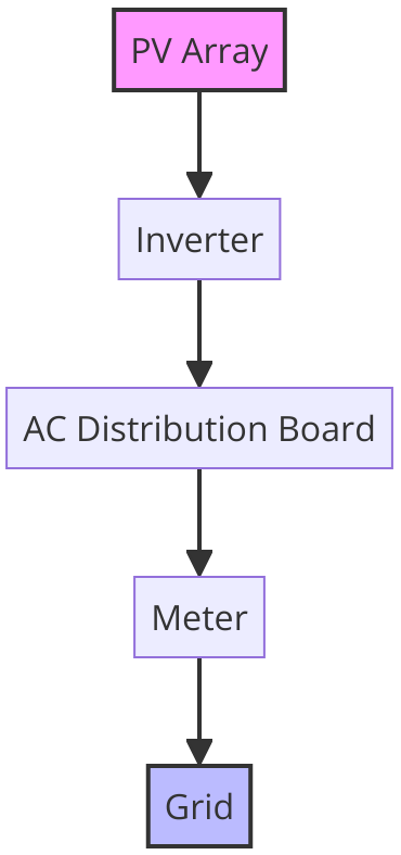
A grid-connected PV system typically includes the following components:
- PV array: solar modules connected into strings and arrays to produce d.c. electricity.
- Inverter: converts d.c. electricity from the PV array into a.c. electricity compatible with the installation and grid.
- AC distribution board: distributes inverter output to local loads and the grid connection point.
- Meter: measures electricity generated, exported, and, where applicable, imported.
- Grid: the public distribution network to which surplus generation may be exported.
UK grid connection compliance
In the UK, PV systems connected in parallel with the public distribution network are generally governed by the Energy Networks Association Engineering Recommendations G98 and G99. Requirements should always be confirmed with the relevant distribution network operator because the process and documentation depend on the specific installation.
- G98: typically applies to smaller generation equipment up to 16 A per phase, approximately 3.68 kW single-phase or 11.04 kW three-phase.
- G99: applies to larger generation installations, installations above the G98 threshold, or installations that otherwise do not meet G98 requirements.
G98 and G99 address issues such as synchronisation, anti-islanding protection, fault-level contribution and power quality. Compliance is required to ensure the PV system operates without adversely affecting the distribution network or other users.
Cable design considerations for PV systems
- D.C. string voltage and current under design conditions.
- Cable current rating, ambient temperature, grouping and installation method.
- D.C. and a.c. voltage drop limits.
- Short-circuit withstand and protective-device coordination.
- UV exposure, outdoor routing, mechanical protection and connector suitability.
- Grid connection requirements and inverter export limits.
For related cable calculations, see Cable Sizing, Voltage Drop, Fault Current Calculations and Solar Radiation Effects.