
Earth fault loop impedance is the impedance of the path followed by earth-fault current from the source, through the line conductor, the fault, the protective conductor or return path, and back to the source. It determines how much fault current will flow and whether the protective device can disconnect within the required time.
The topic links directly to Circuit Protective Conductor (CPC) selection and Fault Current Calculations.
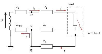
Earth fault loop path
The earth fault loop impedance, Zs, is commonly represented as:
| Zs | Earth fault loop impedance, ohm |
| Ze | External earth fault impedance, ohm |
| Z1 | Line conductor impedance, ohm |
| Z2 | CPC or return-path impedance, ohm |
The external impedance depends on the upstream network. The CPC impedance depends on the protective conductor arrangement, such as armour, a separate conductor, trunking or another permitted metallic path.
BS 7671 disconnection requirements
BS 7671 uses earth fault loop impedance as part of automatic disconnection of supply. The protective device must operate within the required time for the circuit type and system earthing arrangement. Always confirm the applicable values against the current edition of the wiring regulations and the project specification.
| System | 50 V < Uo ≤ 120 V a.c. | 50 V < Uo ≤ 120 V d.c. | 120 V < Uo ≤ 230 V a.c. | 120 V < Uo ≤ 230 V d.c. | 230 V < Uo ≤ 400 V a.c. | 230 V < Uo ≤ 400 V d.c. | Uo > 400 V a.c. | Uo > 400 V d.c. | Other circuits, a.c. or d.c. |
|---|---|---|---|---|---|---|---|---|---|
| TN | 0.8 s | NA | 0.4 s | 1 s | 0.2 s | 0.4 s | 0.1 s | 0.1 s | 5.0 s |
| TT | 0.3 s | NA | 0.2 s | 0.4 s | 0.07 s | 0.2 s | 0.04 s | 0.1 s | 1.0 s |
For TT circuits incorporating equipotential bonding in accordance with the relevant BS 7671 requirements, TN disconnection times may apply. For TN distribution circuits and circuits not covered by the table, a disconnection time not exceeding 5 s is generally permitted. For TT distribution circuits and other circuits not covered by the table, a time not exceeding 1 s is generally permitted.
For TN and TT systems, protective-device characteristics should satisfy:
For an IT system with a second fault, where the neutral or mid-point conductor is not distributed:
Where an RCD is used for fault protection, the following condition is also relevant:
| Ia | Current causing operation of the protective device within the specified time, A |
| U0 | Nominal a.c. or d.c. line voltage to earth, V |
| Cmin | Minimum voltage factor, typically 0.95 |
| RA | Sum of the earth electrode and protective conductor resistance, ohm |
| IΔn | Rated residual operating current of the RCD, A |
External fault loop impedance
In myCableEngineering, the external earth fault loop impedance Ze is calculated in complex form using source earth-fault data entered by the user:
| IE | Source earth fault level, A |
| pfE | Source fault power factor |
| Ik2E | Source earth fault current in complex form, A |
| U | Phase voltage, V |
| U0 | Line-line voltage, V |
| Ze | Source or external impedance, ohm |
Cable loop impedance
myCableEngineering calculates positive and zero-sequence impedance in accordance with IEC 60909. For a line-to-earth short circuit, with Z2(60909) = Z1(60909), the fault current is:
The common earth fault loop impedance terms can be related to IEC 60909 sequence values as follows:
| EFL term | IEC 60909 equivalent |
|---|---|
| Ze | Ze |
| Z1 | Z1(60909) |
| Z2, single-phase system | Z1(60909) |
| Z2, three-phase system | Z1(60909) + Z0(60909) |
Total loop impedance and fault level
After the source and cable impedance components have been obtained, the total loop impedance and load-end fault current are:
The earth fault loop impedance is the magnitude of Zt. For common configurations, myCableEngineering calculates a maximum allowable earth fault loop impedance, although this can be overridden by the user. For other configurations, the required maximum value should be entered by the user.
CPC and protective device checks
The cable armour may be used as the CPC in the calculation of zero-sequence impedance and earth fault loop impedance. The user may also add an additional conductor in parallel with armour to form the CPC, either internal or external to the cable.
Protective conductor sizing should be checked against the relevant wiring regulation, including minimum sizes and thermal withstand. Protective-device settings and any RCD settings must also be checked to confirm the required disconnection condition is met.
For related topics, see Circuit Protective Conductor (CPC), Fault Current Calculations and Cable Thermal Withstand.
For the broader IEC 60909 short-circuit formula set, see IEC 60909 Fault Calculations.
For converting external fault level data into source impedance, see Network Fault Level.
For the positive and zero sequence cable impedance formulae behind loop calculations, see Cable Impedance.