
IEC 60287-2-2 gives methods for obtaining reduction, or derating, factors for cables installed in free air and protected from solar radiation. The methods are principally intended for multicore cables or single-core cables in trefoil, but may be extended to other arrangements where appropriate.
This article summarises the grouped-in-air derating method and the main symbols used in the calculation. For design work, use the relevant edition of IEC 60287-2-2 directly.
Symbols
| De | External diameter of multicore cable, or one single-core cable in trefoil, mm |
| e | Clearance between adjacent cables in a group, measured between surfaces, mm |
| Fg | Group reduction factor |
| h | Heat dissipation coefficient used for thermal resistance calculation, W·m-2·K-5/4 |
| hg | Heat dissipation coefficient of the hottest cable or circuit in a group, W·m-2·K-5/4 |
| hi | Heat dissipation coefficient of an isolated cable or circuit, W·m-2·K-5/4 |
| Ig | Rating of the hottest cable in a group, A |
| It | Rating of one cable or circuit assumed to be isolated, A |
| k1 | Surface temperature rise factor |
| T4g | External thermal resistance of the hottest cable in a group, K·m/W |
| T4i | External thermal resistance of one cable assumed to be isolated while carrying It, K·m/W |
| W | Power loss from isolated cable, or circuit in trefoil, carrying It, W/m |
| Θc | Conductor temperature used for calculating It, °C |
| Θa | Ambient temperature used for calculating It, °C |
Reduction factors for cables grouped in air with existing ratings
Where the sustained current rating for an isolated cable or circuit is known, the rating of the cable installed within a group of similar cables is:
The group reduction factor, Fg, is calculated from:
The surface temperature rise factor is:
The term T4g/T4i is derived iteratively from the ratio hi/hg:
Starting with:
Values for hi/hg are obtained from the data section below.
Reduction factor for IEC 60287 calculated ratings
When IEC 60287 is used directly to calculate sustained current ratings, IEC 60287-2-2.1 gives methods for calculating thermal resistance. To apply group derating for cables, substitute the heat emission coefficient h with the group heat emission coefficient hg:
Again, values for hi/hg are taken from the data section below.
Clearance values to avoid rating reduction
The data for calculating reduction coefficients also gives the conditions that need to be achieved to avoid applying group derating.
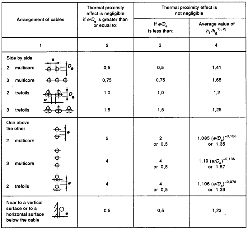
Where cables are arranged in both horizontal and vertical planes, the sustained current capacity should be derived using values of hi/hg for the vertical plane.