
Appendix 4 of BS 7671 provides tabulated values for current-carrying capacity and rating factors for selecting low-voltage cables. Calculation begins with the circuit design current and the protective device, identifies the appropriate cable table and installation method, and adjusts the tabulated rating for the actual installation conditions.
This article describes the method and gives a worked example. It complements the BS 7671 Voltage Drop Calculations and broader Cable Sizing Standards: BS 7671, ERA 69-30 and IEC 60502 article.
What is the current-carrying capacity of a cable?
Current-carrying capacity is the current a cable can carry continuously under specified conditions without exceeding its permitted conductor temperature. The same conductor size can have different ratings depending on its insulation, installation method, ambient temperature, and proximity to other loaded cables.
A table value is therefore a starting point. It represents the conditions stated in that table and its notes; it is not automatically the cable rating for every installation.
Design current, protective-device rating and cable rating
| Symbol | Meaning |
|---|---|
| Ib | Design current of the circuit in normal service. |
| In | Rated current or current setting of the protective device. |
| It | Tabulated current-carrying capacity for the selected cable and reference installation conditions. |
| Iz | Current-carrying capacity under the actual installation conditions. |
| I2 | Current that causes the overload protective device to operate within its conventional time. |
Where overload protection is required, the basic coordination conditions are:
Ib ≤ In ≤ Iz
I2 ≤ 1.45 Iz
The first condition relates the load, protective device, and cable. The second checks the overload operating characteristic. For the protective devices identified in Appendix 4, selecting Iz> In satisfies the second condition; other devices require their characteristics to be considered.
Select the correct BS 7671 table
Before looking up a current rating, establish:
- Conductor material and cable construction, including single-core or multicore and armoured or unarmoured cable.
- Insulation type and permitted conductor temperature, for example 70 °C thermoplastic or 90 °C thermosetting insulation.
- Number of loaded conductors and the circuit arrangement.
- Installation method, such as conduit, trunking, clipped direct, cable tray or burial.
- For single-core cables, the relevant touching or spaced arrangement and flat or trefoil formation.
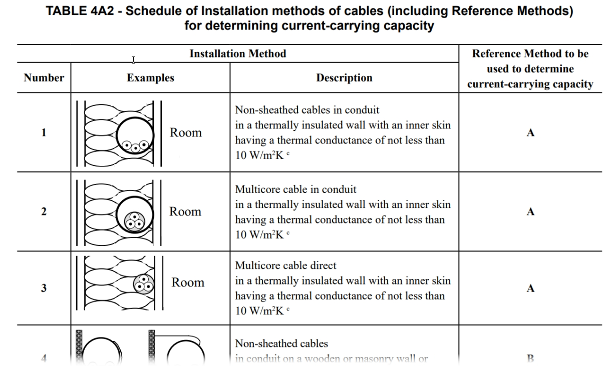
Use Table 4A2 to identify the installation arrangement and its reference method, then select the corresponding current-capacity table and column. Read the table notes as part of the selection. A cable installed in an enclosure or surrounded by thermal insulation cannot simply be assigned a free-air rating.
A 90 °C insulation rating also does not establish that connected terminals or equipment can operate at 90 °C. Check the temperature limits at connections and select the rating basis accordingly.
Apply the relevant rating factors
Appendix 4 ratings use reference ambient temperatures of 30 °C for cables in air and 20 °C for cables in the ground. Conditions that differ from the table assumptions may require correction.
| Factor | Purpose | Reference or consideration |
|---|---|---|
| Ca | Ambient temperature | Tables 4B1 and 4B2, as applicable. |
| Cg | Grouping | Relevant grouping table in the 4C series; check spacing, arrangement and table notes. |
| Ci | Thermal insulation | Applicable insulation arrangement and BS 7671 requirements. |
| Cs | Soil thermal resistivity | Table 4B3, where applicable. |
| Cd | Depth of burial | Table 4B4, where applicable. |
Use only factors applicable to the selected table and installation. Check whether the tabulated ratings already include an effect before applying an additional factor. Assess the limiting section where installation conditions change along the route and take the worst case.
For an above-ground cable without significant harmonic effects, the relationship can be written as:
Iz = It × Ca × Cg × Ci
For a buried cable, include applicable soil-resistivity and burial-depth factors. Grouping factors assume specific assumptions about cable sizes, loading and arrangement; mixed sizes or unusual layouts may require a more detailed assessment.
Calculate the required tabulated rating
For the straightforward above-ground case, with an overload protective device of the type identified in Appendix 4 and no additional protective-device factor:
It,required = In / (Ca × Cg × Ci)
Select a cable whose tabulated rating is at least this calculated value. Using In, rather than Ib, matters: a cable may carry the normal load adequately but still be too small for its overload protective device.
Protective-device and buried-circuit factors
Appendix 4 also identifies Cf for a BS 3036 semi-enclosed fuse and Cc for buried circuits. In the applicable cable-selection procedure, Cf is 0.725 for a BS 3036 fuse, and Cc is 0.9 for a cable buried directly or in a duct in the ground; otherwise the respective factor is 1.
The general selection expression for groups liable to simultaneous overload is:
It,required = In / (Cg × Ca × Cs × Cd × Ci × Cf × Cc)
Appendix 4 gives alternative procedures where grouped circuits are not liable to simultaneous overload, and where overload protection may be omitted under the specified regulations. Use those procedures only when their conditions are established.
BS 7671 current-carrying capacity worked example
Consider a balanced three-phase circuit with a design current of 60 A, protected by a 63 A circuit breaker to BS EN 60898-1. A multicore armoured copper cable with 90 °C thermosetting insulation is installed as a single circuit on a perforated tray, using Reference Method E.
Assume three loaded conductors, an ambient temperature of 35 °C, and no significant harmonic neutral current. For this example, the connected equipment is suitable for the selected conductor-temperature basis.
| Item | Value |
|---|---|
| Design current, Ib | 60 A |
| Protective-device rating, In | 63 A |
| Reference method | E |
| Selected conductor size | 10 mm² |
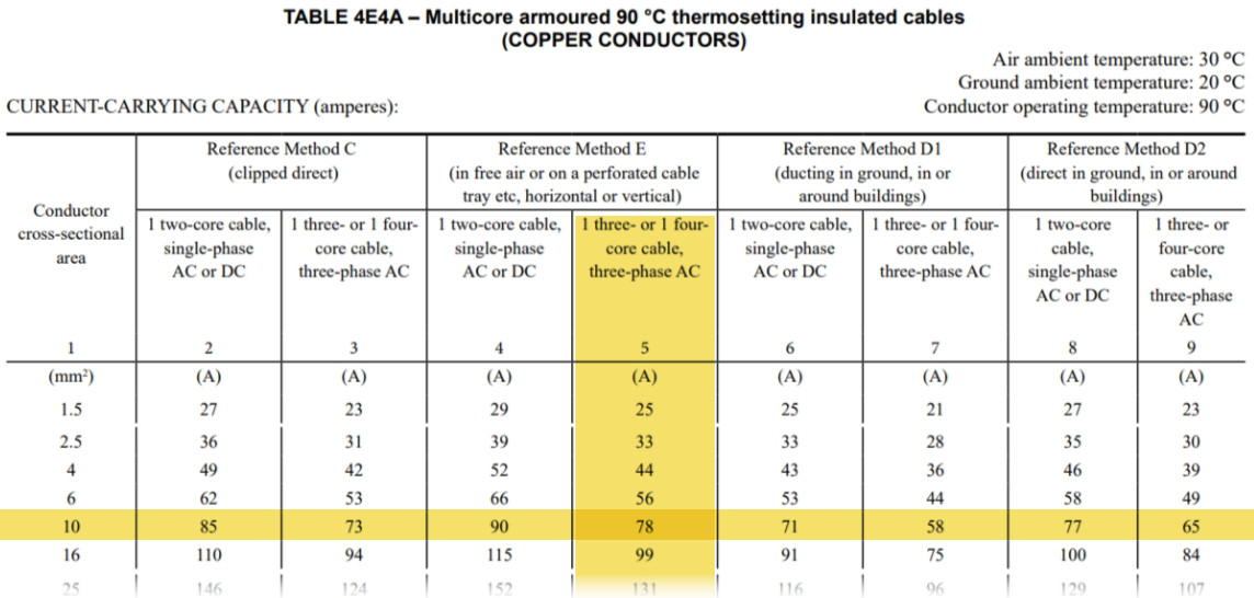
| Tabulated rating, It | 78 A, Table 4E4A, Reference Method E, three loaded conductors |
| Ambient factor, Ca | 0.96, Table 4B1 for 90 °C insulation at 35 °C |
| Grouping factor, Cg | 1.00: single circuit |
| Thermal-insulation factor, Ci | 1.00: no surrounding thermal insulation |
Step 1: Calculate the required table rating
It,required = 63 / (0.96 × 1.00 × 1.00) = 65.625 A
Step 2: Select the smallest conductor size that meets the required table rating
Reading down the Reference Method E, three-phase column of Table 4E4A, 6 mm² has a tabulated rating of 56 A, which is below 65.625 A. The next standard size, 10 mm², is rated at 78 A and passes. Select 10 mm² for the current-carrying capacity and overload checks. The 16 mm² size also passes, but is larger than these checks require.
Step 3: Calculate the capacity under the installation conditions
Iz = 78 × 0.96 × 1.00 × 1.00 = 74.88 A
Step 4: Check overload coordination
60 A ≤ 63 A ≤ 74.88 A
The design current, protective-device rating, and corrected cable capacity satisfy Ib ≤ In ≤ Iz. For the specified circuit breaker, the Appendix 4 overload condition is satisfied by selecting Iz> In.
Result: 10 mm² is the smallest standard conductor size in the selected table column that meets the current-carrying capacity and overload requirements for the stated assumptions. Its corrected current-carrying capacity is 74.88 A. Voltage drop, fault protection, and the remaining circuit-design checks must still be completed and may require a larger conductor.
Harmonics and neutral loading
Balanced fundamental-frequency currents do not necessarily mean the neutral is unloaded. Third-harmonic currents can add in the neutral and increase heating in a four-core or five-core cable.
Appendix 4, Section 5.5 and Table 4Aa, address this situation within stated limits. Depending on the harmonic content, selection may be based on line current or neutral current. Where the neutral is expected to carry more current than the line conductors, it can govern conductor selection. Neutral protection and phase imbalance also need consideration.
Complete the remaining cable-sizing checks
Passing the current-capacity calculation is one part of cable selection. Also check:
- Voltage drop over the complete circuit route.
- Fault-current withstand and protective-device disconnection requirements.
- Protective-conductor sizing and the suitability of any armour used as a protective conductor.
- Terminal temperature limits, mechanical requirements and environmental conditions.
Use the selected cable size and actual installation data in the BS 7671 voltage-drop calculation. A size that meets the thermal requirements may need to be increased to satisfy voltage drop or fault protection.
For project work, our cable sizing software brings current-capacity, voltage-drop, and fault checks together with the supporting cable records and reports.
References
BS 7671:2018+A4:2026, Appendix 4: Sections 2–5; Tables 4A2, 4B1–4B4, the relevant 4C grouping tables, Table 4E4A and Table 4Aa. Use the applicable table notes and the wider requirements of BS 7671 alongside this explanation.