
Good cable installation design is not only about selecting the correct cable size. The route, method of support, duct arrangement, draw pits and pulling limits all affect whether the cable can be installed safely and remain serviceable throughout its life.
This guide brings together practical considerations for cable supports, underground ducts and draw pits. Always check the project specification, manufacturer guidance and the relevant edition of the wiring regulations or local installation standard before construction.
Cable supports on ladder, tray or clips
Where conductors are not continuously supported, they should be fixed at suitable intervals so that the cable is not damaged by its own weight and no strain is placed on terminations. This is particularly important for vertical runs, changes in direction and routes with heavy armoured cables.
The On-Site Guide to BS 7671 gives suggested maximum spacing for cable support clips. The table below is a cleaned-up version of the original guidance used in the knowledge base article.
| Overall cable diameter, d (mm) | Non-armoured sheathed cables: generally | Non-armoured sheathed cables: in caravans | Armoured cables | Mineral-insulated copper or aluminium sheathed cables | ||||
|---|---|---|---|---|---|---|---|---|
| Horizontal | Vertical | Horizontal | Vertical | Horizontal | Vertical | Horizontal | Vertical | |
| d <= 9 | 250 | 400 | 250 | 400 | – | – | 300 | 800 |
| 9 < d <= 15 | 300 | 400 | 250 | 400 | 350 | 450 | 900 | 1200 |
| 15 < d <= 20 | 350 | 450 | 250 | 400 | 400 | 550 | 1500 | 2000 |
| 20 < d <= 40 | 400 | 550 | 250 | 400 | 450 | 600 | – | – |
- For cables with an overall diameter exceeding 40 mm, follow the manufacturer’s recommendation.
- For flat cables, take d as the dimension of the major axis.
- The spacings for horizontal runs may also be applied to runs at an angle of more than 30 degrees from vertical. For runs at 30 degrees or less from vertical, use the vertical spacing.
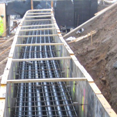
Underground cable ducts
Underground cable ducts provide protected routes for power, control, communication and fibre optic cables. A well-designed duct system makes cable installation easier, protects the cables in service and allows future maintenance or expansion.
Planning, permits and existing services
Plan the duct route before excavation, including depth, separation between ducts, cable type, draw pit positions and space for future expansion. Obtain any required permits and confirm right-of-way, environmental and utility requirements before work begins.
Existing buried services should be identified and located before digging. This reduces the risk of damage to gas, water, telecoms or other electrical services, and is essential for worker safety.
Soil conditions, duct materials and thermal performance
Soil conditions influence the duct installation method, depth, bedding, backfill and long-term stability. Common duct materials include PVC, HDPE and fibreglass, with installation methods such as open trenching, directional drilling and microtrenching.
Bedding and backfill should protect ducts from ground movement and large loads. Duct spacing and surrounding materials also affect cable current-carrying capacity and operating temperature, so maintain adequate separation and use suitable thermally conductive backfill where required by the design.
Install warning tapes or marker posts to help future excavators identify buried ducts and cables. Where needed, design the duct system with drainage and ventilation to reduce the risk of water or gas accumulation.
Draw pits and cable pulling
Draw pits, also called draw boxes or access chambers, provide access points along an underground cable route. They simplify cable pulling, reduce installation tension and allow maintenance or repair access after installation.
- Location: place draw pits at regular intervals and at changes in direction, elevation or duct size.
- Size: provide enough space for the number of cables, splices and installation equipment.
- Design: include suitable drainage, ventilation and secure access covers.
- Material: use materials, such as concrete or polymer concrete, suited to the expected loads and environment.
- Safety: follow safe working procedures for access chambers, including confined-space controls where applicable.
Maximum cable pulling length
The maximum distance between draw pits depends on project-specific factors, including cable type, bending radius, tensile strength, trench or conduit conditions, route complexity, cable weight and the pulling equipment available.
For a straight pull, a simple estimate of pulling tension is:
and therefore:
| L | Length of the cable pull, m |
| T | Maximum pulling tension, N |
| W | Weight of the cable per unit length, N/m |
| f | Coefficient of friction between the cable and the conduit or trench |
To convert a cable mass in kg/m to a force in N/m, multiply by the acceleration due to gravity, approximately 9.81 m/s2.
Once the expected pulling tension has been calculated, compare it with the cable manufacturer’s permitted tensile strength. If the expected tension is too high, reduce the distance between pits, reduce friction, change the pulling method or adjust the route.
Bend multipliers
For a curved section, the following multipliers may be applied to the tension calculated for the preceding straight section. These multipliers are based on a friction coefficient of 0.5.
| Bend angle, degrees | 15 | 30 | 45 | 60 | 75 | 90 | 105 | 120 |
|---|---|---|---|---|---|---|---|---|
| Multiplier | 1.14 | 1.30 | 1.48 | 1.70 | 1.94 | 2.20 | 2.50 | 2.86 |
If the coefficient of friction differs from 0.5, the multiplier should be adjusted for the actual installation conditions. Pulling around bends also creates sidewall pressure, so the pressure at bends must be kept within the cable manufacturer’s specified limits.
Quality assurance and safety
Inspect the installation as it progresses to confirm that the duct system, supports, draw pits, bedding and backfill meet the specification. Keep accurate as-built records showing duct routes, depths, draw pit positions and installed cables.
Use suitable cable-hauling equipment, techniques and lubricants to prevent installation damage. Ensure all personnel understand the hazards associated with excavation, lifting, cable pulling and working in or around access chambers.